Basic Operations With the Compass; 2 Angle Bisectors
In “Where DO Patterns Come From”? we will encounter the “divided circles.” A divided circle is the basis of all pattern. Creating them requires dividing angles rather than lines. The first case to deal with is dividing an isolated angle easily. Then we will move to circles.
Many problems in drawing geometric patterns can be expressed as “How do I turn this question into a triangle where I know about two angles or two sides?” We can approach this task as exactly that question. This is one of those rare cases where this is easy, because we have already learned how to do it. Looking at the problem of dividing an angle in that way will lead us straight to the problem of bisecting a line; dividing an angle is simply a special case of dividing a line. We already know how to do that. An angle bisector is constructed very much like the line bisector but now it will divide an angle in half.
More Complex cases also arise
Many pattern constructions require dividing an angle in a complex layout. Here we need the angle bisector [OC] to find point [G] on the corner of the rosette petal.
We need an easy method that always works and doesn’t make a mess in a layout. This case is reviewed at the end of the discussion.
We first create a triangle with known structure to set up the problem in a way that is already familiar.
Step by Step
I drew a random angle.
87.259° is pretty random.
We want to divide that angle into two equal angles.
The red line through [D] is our goal.
We need to set up something we know a lot about already to solve problems like this.
First: [D] is marked with the protracting pin as a compass center.
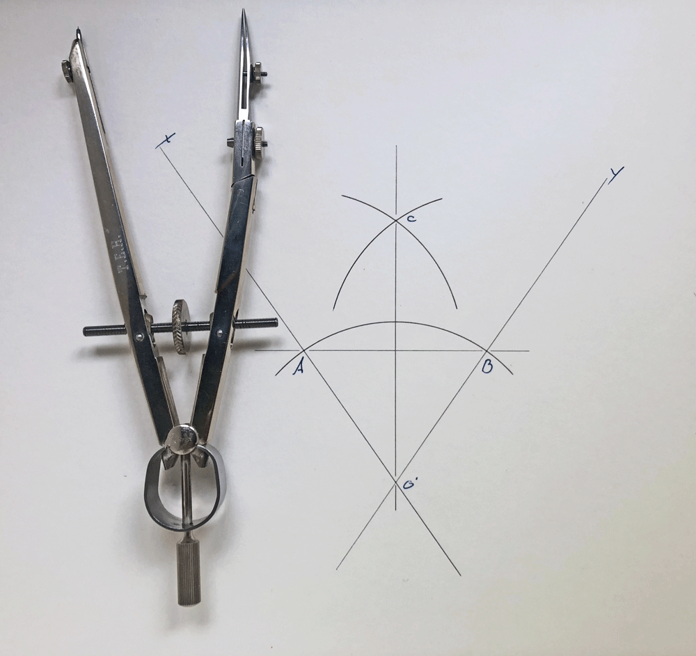
Second: We can draw an arc through both legs of the angle to give new points [A] and [B]. Since this is drawn with a compass, we know that the lines [AD] and [DB] have equal length.
We can put [A] and [B] any convenient place on our drawing. If the two lines forming the angle are short, they can be extended. Keep extensions short, less than 100% of the line length. Long extensions of short lines are an accuracy problem so this is the real limit on where we can put the arc from [A] to [B]. Otherwise we just put it somewhere where we have room to work. Radius X is our choice.
We now have a triangle [ADB]. We have two new compass centers [A] and [B] to be marked with the protracting pin.
If we bisect the line [AB] exactly, we will have bisected the angle ADB exactly. This makes sense from looking at the drawing. I will not give geometric proofs for anything but you can go look these up if you are curious.
We know that point [D] already sits on the bisector line through [AB]. Due to the way we drew this [D] is equal distant from [A] and [B]
Now the bisector of the line is drawn exactly as it was in the discussion of the line bisector. I choose the radius as X here so that it looks exactly like our line bisector.
You will see an example below where we can use any length for the radius of the two arcs from [A] and [B] so long as they are equal.
The new point [C] is marked with the protracting pin and a line is drawn from [C] to [D]. The line [AB] is bisected, and the angle ADB is bisected.
The secret was creating a problem to which we already know the answer. If you master accurate practical examples of these two simple constructions, you will be able to draw almost all of the patterns discussed here.
Tidiness
As for the line, only some of this needs to be marked on the drawing. Enough of each arc is drawn to define the points we need.
Practically: This is quite fast and usually quite accurate.
Make the lengths to [A] and [B] as long as possible without overextending your angle line layouts. Using a longer radius to find [C] is a bit more accurate. It need not be the same as the radius used for [A] and [B].
The Real World Example
Working in a crowded layout.
This will follow exactly the sequence described above.
We need the angle between the two red lines bisected.
We will use that bisector inside the red circle for defining the taper of the rosette.
Exactly as described above
The radius for the first arc through [A] and [B] was chosen to put the construction inside the pattern where I had open space.
If you look back at the unmarked picture, you will see only four small marks to define [A] [B] and [C]. This construction is very tidy.
If the inside of the angle is just too crowded, there is another option.
It is equally valid to extend the pattern lines defining the angle and construct the bisector on the back side of the angle.
Everything else is the same.
This construction should be very precise. If you have identified your points carefully, marked them with a protracting pin, the division should be exact to your ability to measure it. This is still used in precision machine work to construct layouts.
The next post will be a short diversion to see how your mastery of the compass is progressing. A fairly demanding exercise is very revealing.
For the post after that one we will return to one of the enormous number of places where this angle bisector construction is used in geometric pattern layout; the divided circle.
v0 20/5/24


